Steam is a very efficient and easily controlled heat transfer medium. It is most often used for transporting energy from a central location to any number of locations in the plant, where it is used to heat air, water or process applications. It is important to get steam to its various users around the plant as efficiently as possible. Efficiency translates into getting steam to the users with minimal loss in latent energy at a reasonable cost. This is where Steam Traps go into action.
A Steam Trap is simply an automatic valve that opens for condensate, air and CO2 and closes for steam. Without steam traps the condensate would form in distribution piping, creating problems.In identifying steam traps we can break them down into three main groups: Thermodynamic, Thermostatic, Mechanical.
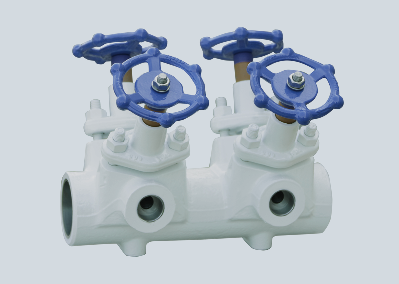
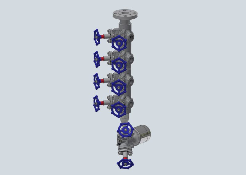
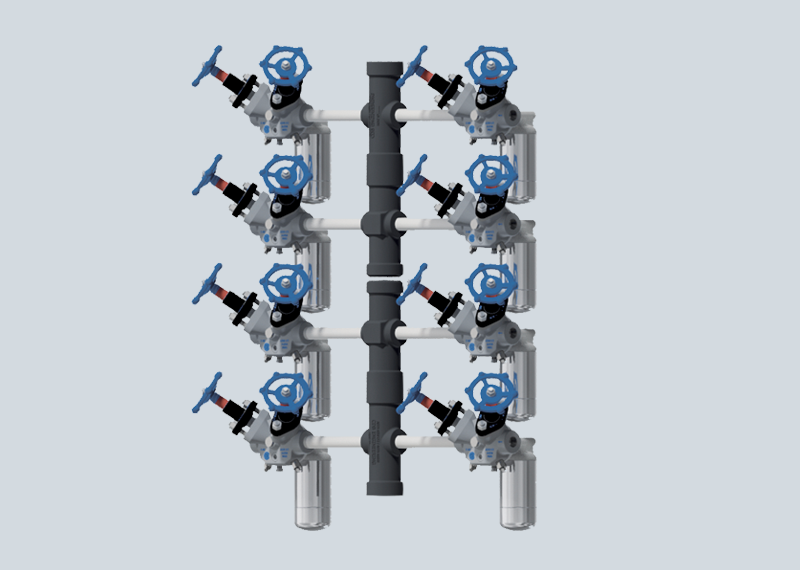
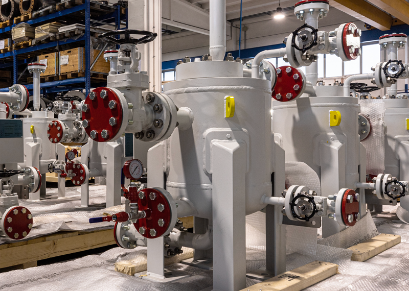
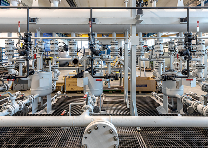
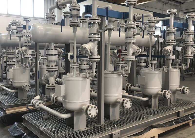
In order to manage steam properly, amongst very few others in the world, CDB also supplies forged Piston Manifolds equipped with trap stations and condensate lift pumps to return the condensate back to the boiler for reuse.
Steam Line
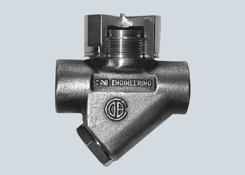
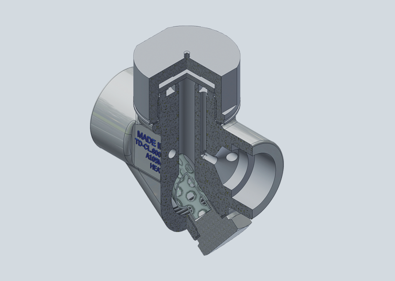
Thermodynamic Steam Trap –
Disc Type (TD)
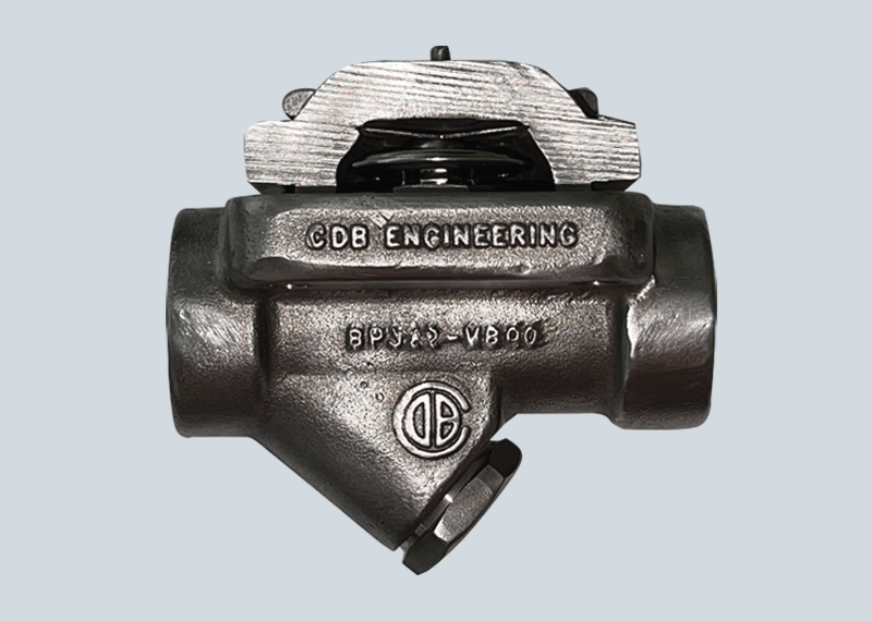
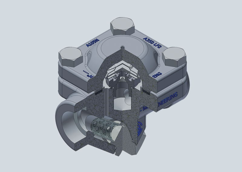
Thermostatics Steam Trap –
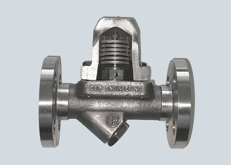
Balanced Pressure Type (BP)
The operating principle is based on the balance between the steam pressure and the internal pressure of the thermostatic membrane capsule, hermetically sealed and filled with a volatile fluid whose saturation temperature is lower than steam at any pressure. At start up the trap is wide open, freely discharging air, non-condensable gases and cool condensate. When the steam reaches saturation temperature, vaporization of the liquid inside the capsule creates a pressure differential which will shut the discharge orifice thus preventing any steam loss. When condensate inside the trap cools, the vaporized filling inside the capsule condenses thus reducing the internal pressure allowing the opening of the trap for discharge again.
Thermostatic Steam Trap –
Bi-Metallic Type (BM)
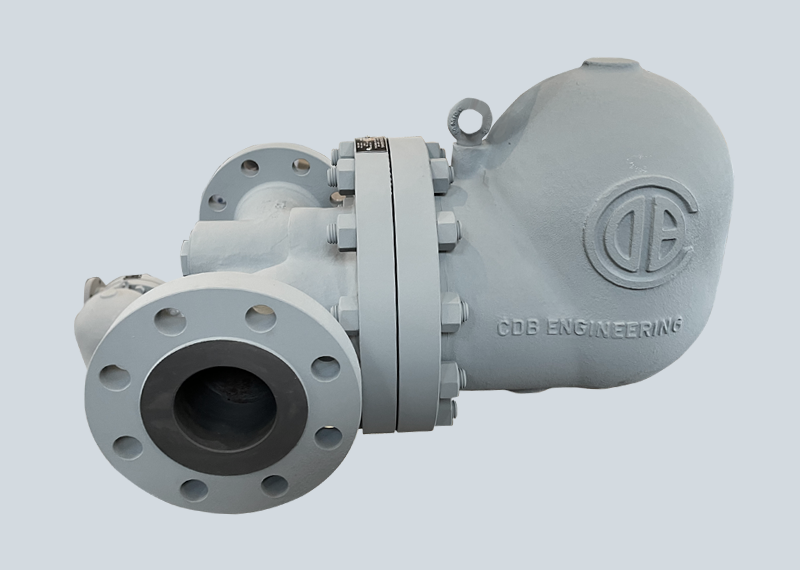
Mechanical Steam Trap –
Float + Thermostatic Type (FT)
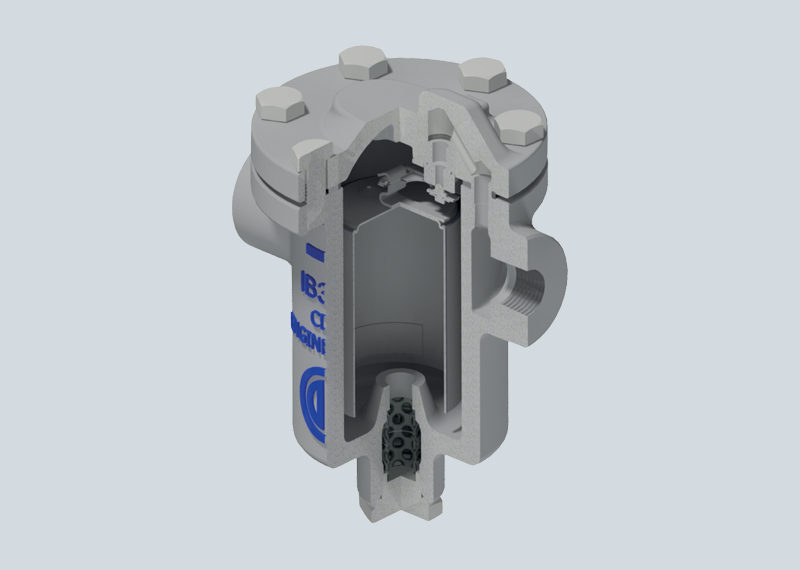
Mechanical Steam Trap –
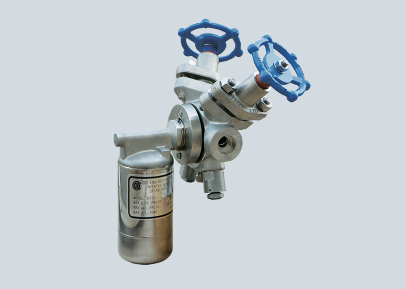
Inverted Bucket Type (IB)
The inverted bucket traps respond to the difference in density between steam and condensate and operate on the principal of an inverted water glass (the component referred to as the bucket). The inverted bucket is attached on the valve head by a lever mechanism and operated to open and close the trap. On start-up the bucket, by its own weight, rests on the trap bottom and the valve is open discharging air and non-condensable. When reaching the trap, condensate makes the bucket float (because of air inside) and rise until it closes the discharge orifice. A small hole in the top of the bucket allows air vent and let condensate in until the bucket slowly sinks to the trap bottom opening the valve. Condensate is discharged until steam enters the trap filling the bucket which rises and closes the trap. Steam will be vented through the hole in the bucket and the cycle is repeated providing an intermittent type discharge.
Piston
Manifolds
Trap Stations and Universal
Connection Steam Traps
Condensate
Lift Pumps
Condensate
Lift Systems
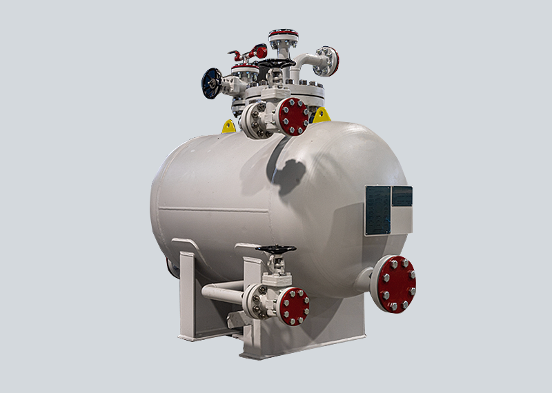
Turn key Condensate lift packaged systems are supplied fully customized with the number of pumps required to meet the required condensate load. In order to collect condensate from the recovery lines and send it to the pumps, a vented receiver tank is mounted on a common base along with all the necessary valves and ancillaries such as y strainer, sight glasses (all fully manufactured by CDB)

